PCB Prototype Assembly
How Reliable your PCBs are – Laminates Using High Tg Material
Construction methods of Printed circuit boards (PCBs) are essentially similar, although their constituent materials and the intrinsic quality of their surfaces may differ. These differences affect the durability and functionality of the PCB throughout its life and this may be critical to the application.
Essentially, the PCB should exhibit a reliable performance, whether it is in the manufacturing stage, in the assembly process, or in actual use. Apart from the additional costs incurred for correcting defects in the assembly process, there may be failures in actual use, resulting in claims. From this point of view, the cost of a high-quality PCB may be considered negligible.
Over the years, there has been considerable progress in the development of laminates used in the industry, leading to an improvement in the reliability of PCBs. Introduction of lead-free soldering, very high layer count, environmental issues, and electrical concerns have led to placing greater attention to the PCB materials.
To address the above issues, the laminate industry has introduced several products in the market. However, they all come with their own trade-offs, and there is no one perfect laminate to address all the issues. Users need to look at the pros and cons of each PCB laminate, and select the product that best fits their requirements.
Reliability of the PCB actually depends on the proper selection of the material for the laminate. Three parameters are crucial here—the glass transition temperature (Tg), Coefficient of thermal expansion (CTE), and the decomposition temperature (Td).
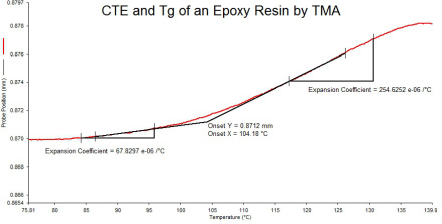
Glass Transition Temperature (Tg)—This is an important parameter for the base material, as it determines the temperature at which the resin matrix changes over from a firm, non-elastic condition to a soft, elastic one.
The TG value for the base material actually sets an upper temperature boundary, where the resin matrix starts to decompose and subsequently the PCB delaminates. Therefore, Tg is not the maximum operational temperature for the PCB, but rather one the material can endure for only a very short duration.
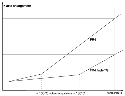
Coefficient of Thermal Expansion (CTE)—this parameter shows the thermal expansion of the base material of the laminate, especially the absolute expansion in its z-direction. This value is of importance for the stability of vias. With a low CTE-z value, several reliability issues are reduced, such as cracks within the via, corner cracks, and pad lifting. Mostly,
Decomposition Temperature (Td)—this parameter depends on the energy of binding within the polymers in the resin system of the laminate, rather than on the laminate’s glass transition temperature. In the industry, this characteristic is usually indicated at one of two temperatures 260°C or 288°C, and expressed as the time to delamination of the tested material at either temperature. The time to delamination at a certain temperature is a very important indicator of the heat resistance of the lamination, considering the temperature profile for the lead-free solder reflow process often maximizes at 260°C.
Td indicates the temperature at which the base material loses 5% of its weight and is an important parameter of the thermal stability of the base material. Exceeding this temperature causes irreversible degradation and damages the material by decomposition.
Interrelation between the Parameters
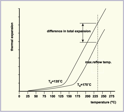
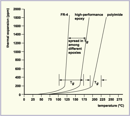
Although knowing the individual numbers for each of the three parameters for a laminate is a good reference, their interdependence is more important. Although it is preferable to have a laminate with a higher Tg, a thermal expansion curve of the laminate offers a better understanding. If the thermal expansion curve shows an extremely high CTE beyond the Tg temperature, it reverses the benefits of a high Tg value.
To understand this, consider the parts of the laminate where metals join the epoxy resin, such as copper traces and vias on the PCB. If the difference in the CTE between the two materials is high, there is a danger of the copper peeling away, and vias developing a crack in their barrels, once the temperature crosses Tg.
During lead-free soldering, the reflow temperature is typically 240-260°C, which is well beyond the Tg of most PCB materials. With very high CTE, even high Tg PCB materials will be unable to survive a soldering process. Therefore, a reliable material well suited to lead-free soldering must have a high Tg value along with a minimal transition of CTE values through Tg, followed with a relatively low CTE beyond the Tg value.
It is also important to look at the CTE value of the material in the x-y plane. Ideally, this value should match that of copper, but considering the complexities of laminates, it is much higher. Practically, a CTE value of 70 ppm/°C is satisfactory, although a lower number is better.
Although not much importance is placed on the Td value of a laminate, it can be a good indicator for the performance of a lead-free soldering process. As the temperature rises during the reflow process and approaches the Td, the resulting mass loss can develop stresses within the PCB material, and this can contribute to delamination. Therefore, materials with Td near the lead-free soldering temperatures may be a reliability concern. Although the material may not actually be losing enough mass for decomposition, the loss may be enough to cause a significant stress build-up.
Practical studies indicate materials with Td of 300°C often have problems with lead-free soldering, whereas materials with a Td of 400°C did not. At the same time, materials with lower Td also demonstrate a higher CTE, aggravating the issue at lead-free soldering temperatures.
Conclusion
Understanding Tg, CTE, and Td for a material and their interactions is very important for the reliability of lead-free soldering for a PCB, especially as it also involves the peel strength issues of the PCB at lead-free soldering temperatures.
Top 10 High Quality Power Stencils in India, PCB Manufacturing Services, Turnkey PCB Manufacturer in India, PCB Prototype Manufacturer, PCB Fabrication and Assembly, PCB Cost Calculator, Buy Electronic Components Online, High Frequency Power Stencils in India, PCB Fabrication Services in India, Printed Circuit Board in India, Fabrication PCB, PCB Board, PCB Production, PCB Order, PCB Prototype, PCB Manufacturer, PCB Prototype Manufacturer, PCB Prototype Assembly, PCB Low Cost, PCB Prototype Fabrication, PCB Manufacturing, PCB Prototype Low Cost, Prototype PCB Board Manufacturer, PCB Manufacturing Service, Prototype Circuit Board Manufacturers, Cest PCB Prototype Service, PCB Manufacturing in India, PCB Fabrication Process, PCB Board Material, How to use Printed Circuit Board, How to use PCB Fabrication, PCB Online calculator, PCB Electronic Circuit Board, PCB Assembly Process, PCB Online Store, PCB Component Sourcing Material, PCB Power, PCB Power Login, PCB Manufacturing, PCB Fabrication, PCB Online, Online PCB design, PCB Power supply, PCB electronics, PCB design India, PCB Board price in India, PCB Service, PCB Maker, PCB Stencil, Power Circuit Board, PCB Printing Service, Custom PCB, PCB India, PCB Manufacturing Cost, PCB Order, PCB Online Quote, Buy PCB